
Reference project assembly line with carrier circulation system
Task: component handling, potting, mounting, and testing
The component to be processed is a mechatronic assembly, an injection-molded part with insert, which have to be processed further in different variants. In addition to the application of a Data Matrix code by laser, several cavities created by the injection molding process as well as existing unfilled diode pockets have to be encapsulated with a compound resistant to moisture in workpiece variant 1. In workpiece variant 2, the cavities created by the injection molding process are also encapsulated, diodes are fitted in the diode pockets provided and then encapsulated with silicone. Afterwards, the casting compounds are cured and the workpieces are tested with different test and measuring methods. The workpieces are delivered in special trays, which are also used again later for shipping.
By looking for a competent partner and supplier for the design and construction of a plant for serial production, Hirata Engineering Europe GmbH from Mainz was contacted. Hirata has already been active several times for the conception and construction of similar production systems and in the current case also in the position to fulfill the specifications regarding the desired processes and cycle times as well as the realization of the plant within the given time and cost frame. One of the biggest challenges besides the project duration was the rather limited space available for the whole plant. Everything had to be designed and built as compactly as possible without compromising later accessibility for maintenance.
The customer already has an A1 line (cycle time 12 s) in which such assemblies are manufactured. However, various work steps are still carried out manually and processes such as laser marking, scanning and others are not available. In the new production line (A2), these processes had to be integrated and everything should run fully automatically.

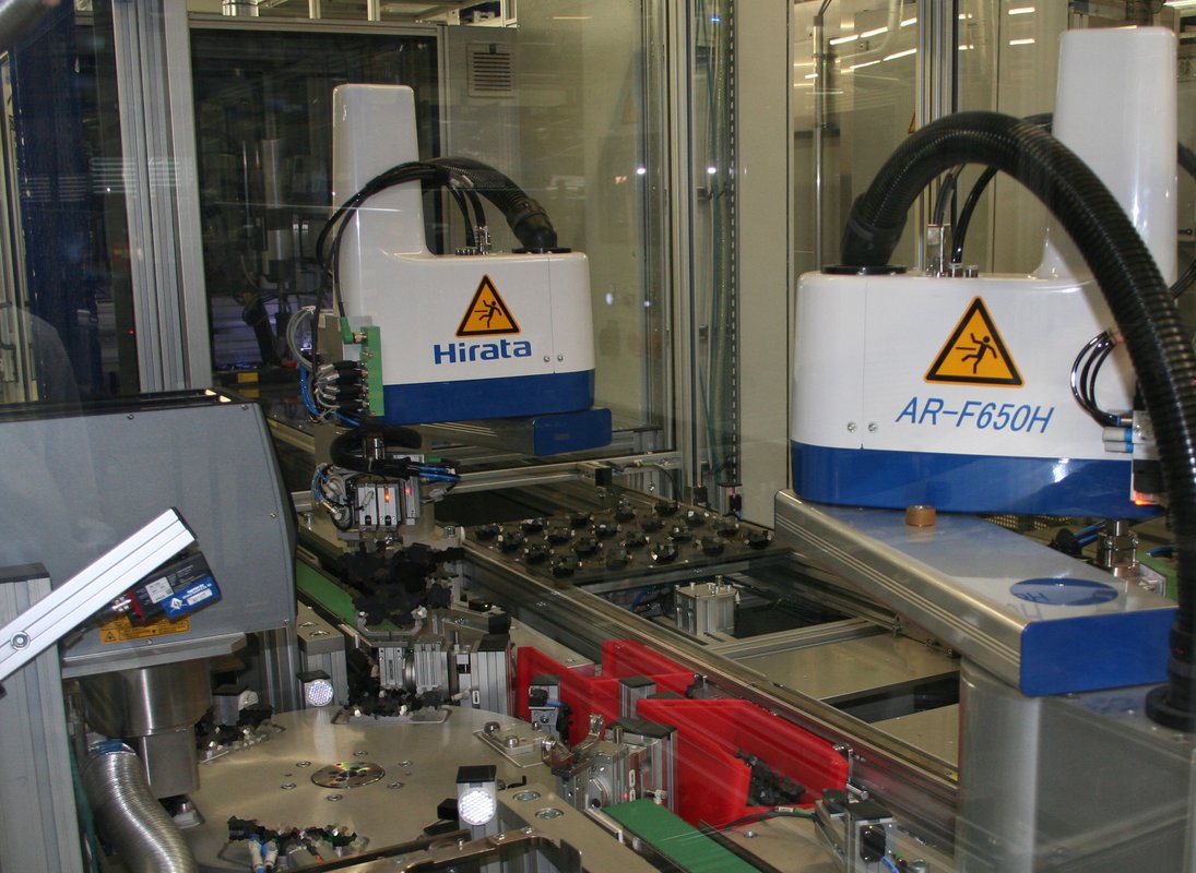
From the trays into the workpiece carrier
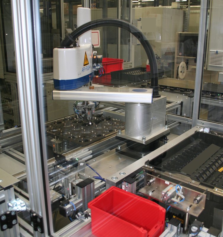
The first station of the line is the loading station, which consists of two parallel palletizers (AST), each equipped with a SCARA robot model AR-F 650. The delivered trays with the products to be processed (approx. 1.5 kg per tray) are fed into the palletizers as tray stacks (approx. 12 kg per stack) by electric lift trucks. In the palletizers either workpieces of different variants or the same workpiece variant in both are provided. Each robot takes "its" vertically positioned workpieces from the trays and brings them to a turning station where they are horizontally aligned for further processing. The workpieces are placed on a rotary indexing table then, which is located between the two robots. Here the products are scanned and the existing supplier code is checked. Now the rotary indexing table places the workpiece under the laser marker, which applies a further code as well as plain text. After checking this marking by scanner, the robot removes the workpiece from the rotary indexing table again and places it in a workpiece carrier with 20 available positions. If the coding is faulty, the workpiece is immediately sorted out and placed on a separate NOK belt.
The loading station is designed in such a way that two different workpieces can be fed into the system simultaneously and in parallel. Each robot only takes care of its own workpiece variant, deposits it in the rotary indexing table and removes it again, in order to deposit it sorted by type in the workpiece carrier provided for this purpose. If only one workpiece variant is to be processed, the robots share the tasks. One robot places the workpieces in the rotary indexing table, the second robot removes them and places them in the workpiece carrier. Now the carrier travel to the encapsulation station, where the punctiform cavities and, depending on the product variant, also the unloaded diode pockets are filled with a red encapsulation compound.

Potting, curing and testing
The loaded workpiece carriers are now transported to three identical casting stations arranged one behind the other. If workpiece variant 2 (including diodes) is used, only the 12 point-shaped cavities are potted and the workpiece carrier is transported to the next station for UV curing. If it is workpiece variant 1 (without diodes), both of the 12 punctiform cavities and the two diode pockets are potted. Once all cavities are sealed, these workpieces are also transported to the next UV curing station. The UV curing is followed by a station for AOI - automatic optical inspection. Here it is checked whether all casting points are correctly cast or whether too little or too much casting compound was applied.
Now the ways separate
After the AOI station, the paths of the two workpiece variants separate. Variant 1 (without diodes) now reaches the continuous furnace arranged parallel to the dosing stations via a cross transport. The casting compound is now thermally cured in the continuous furnace. After the furnace, a short cooling section with fan follows, on which the hot workpieces are cooled down.
The workpieces of variant 2 (including diodes) now take the way to line A3. In this line the cycle time is 12 s. After the electrostatic discharge of the workpieces, the carriers are transported to a dosing station with integrated linear system. Here, silver conductive adhesive is applied into the diode pockets and equipped with diodes in the following station.

Up into the paternoster oven
A lift takes over the workpiece carriers with the loaded workpieces and lifts them to a height of approximately 4 m. At this height, a cross conveyor transports the carriers to the parallel paternoster oven. When designing the corresponding handling unit that places the workpiece-carriers in the furnace, the high temperatures (approx. 150 °C) prevailing at the furnace entrance had to be taken into account. Special materials with low thermal coefficients were used for profiles, bearings, grippers, etc. and care was taken to avoid thermal bridges. The lift works with proven technology, rack and pinion drives and flat track guides, which were also used in Hirata's palletizers.
The paternoster oven used at this location was installed mainly because of the limited space. In contrast to the continuous oven in line A2 it requires a much smaller footprint. The workpieces remain in the oven for 1 h, slowly move down again and discharged there.
Potting and drying
In a further potting station, which is similar in design to the potting stations in line A2, the diode pockets including diodes are now potted with a silicone compound. Now the workpiece carriers are transported back up to a height of 4 m in a second paternoster oven to dry the silicone. At the top, the carriers leave the paternoster oven and are transported on a conveyor belt that runs above the continuous oven of A2. The conveyor belt can be stopped at seven positions so that the workpieces can cool down. At the end of the line a cooling station with a ventilator is also integrated.
Reunited
A lift installed at the end of the cooling section brings the workpiece carriers from line A3 and line A2 together again. This means that, depending on where a carrier is located, at the top at the end of the cooling section of A3 or at the bottom at the end of the cooling section after the continuous furnace of A2, the lift picks up the carrier and transfers it to a test station. Workpieces recognized as NOK parts pass through the station without testing. For OK parts, a current and voltage test is performed on the diodes (variant 2). Then the contacts of the workpieces (variants 1 + 2) are optically checked by means of a wobble circuit test. All NOK workpieces, even those already registered as NOK in other stations, are now placed on a separate belt.
Behind the testing station there is a freely programmable linear axis, which brings the workpiece carriers to different transfer points, depending on the workpiece variant. For variant 1, either the workpiece carriers continue on to the automatic unloading station at the end of the line or to a manual unloading station, or the carriers with workpiece variant 2 are transported to line A1, which is located next door to remove and pack the workpieces.
Automatic unloading and palletizing
The automatic unloading station is similar to the loading station at the beginning of the line, but here only one palletizer and one SCARA robot model AR-F 650 are working. The robot takes the workpiece out of the WT, which is erected again in a swivel device, scanned and placed into the provided tray. Since all workpieces are scanned, the position in which the respective workpiece is placed in the tray is also documented. The empty WTs are transported to a corner transfer unit between the unloading and loading station (A2) and are thus available again for the loading station.
The tray stacks are removed again from the palletizer by electric lift trucks and brought to a manual packing station. Here the trays are checked for completeness. At the same time one workpiece scanned from the loaded tray. The workpieces in the same tray are already documented and therefore they do not have to be scanned separately. In the next step four trays are placed and packed in the corresponding carriers together with a desiccant bag. For the dispatch the same carriers are used for shipping as for delivery.
The production lines working in three shifts. Due to the interlinking and the different cycle times in lines A1 (12 s), A2 (6 s) and A3 (12 s), many thousands of workpieces leave the lines each day by manufacturing with several variants. If only workpiece from variant 1 (without diodes) is produced, the daily output is increased further.
System is controlled by one center
Lines A2 and A3 are controlled by a central line controller. The main line is the A2, where all products are placed and the line controller decides what is processed where. Each station equipped with a SCARA robot or a linear system is controlled by its own multi-tasking controller from Hirata. Also the associated peripheral devices such as lift, conveyor lines etc. are controlled by the system. These Hirata controls communicate with the master computer (line controller), which monitors all processes and organizes the production orders. Due to the networking of the systems, the programming is very complex and requires a lot of know-how. The customer's technicians and engineers have been trained to the extent that certain changes, such as teaching new positions or similar, can be carried out independently. The maintenance personnel is also trained accordingly. If major program changes are required, they are carried out by the specialists at Hirata.
Fast implementation despite special challenges
Approximately 6 months have passed from conception to commissioning of line A2 and another 6 months for line A3, plus 1 to 2 months for on-site optimization with auditing and validation. The implementation of the different processes integrated in the lines was also exciting. Many of them are Hirata's daily bread, others, such as potting, are the domain of the customer. Due to the good cooperation all tasks could be solved optimally. Also the special challenges due to the limited space could be mastered with a lot of experience. Every centimeter counted by determining the station dimensions and the free interior space within the line. After all, it had to be possible to open the control cabinet doors and allow the maintenance personnel a certain amount of freedom of movement. All in all, those responsible at the customer were very satisfied with the fast implementation and the result. The Hirata employees were available almost around the clock in some project phases and Hirata also quickly implemented special requests or subsequent changes.