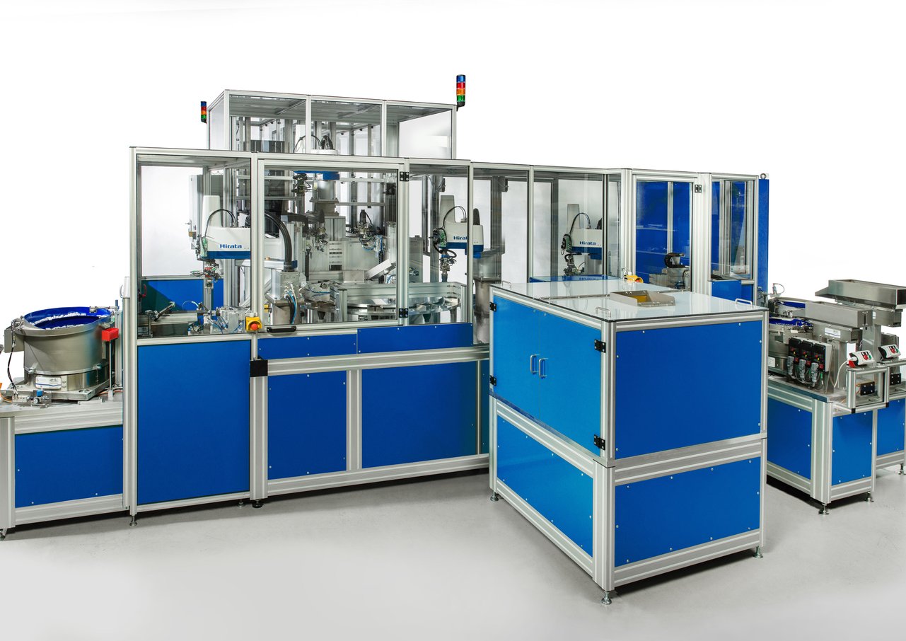
Reference project production cell with rotary table
In the concrete case Hirata Engineering Europe GmbH in Mainz received the order for the construction of an automated assembly for electrical connectors exactly for this reason. The task is to assemble a part of an electrical connector (rear housing part plus clamping roller including spring, clamping roller receiver, latch and grommet). This connector is manufactured in two versions, as a normal one and as low-cost Variations, in three sizes each. The customer's original plan was to produce these parts in two separate units, an assembly island for the strain relief (pinch rollers, springs, pinch roller receiver) and an assembly line for the rear part of the connector housing. Both assembly areas should be connected by a buffer area.
Concept change saves space and money
The experts at Hirata have revised this concept and combined the two originally planned assembly units into one production-/assembly island. Also buffering was not necessary in the work flow and for this reason the scarce floor space could be significantly reduced and the costs could be lowered by using Hirata's own components like SCARA robots and palletizing. A further requirement of the customer was to design a flexible assembly system, so that all connector sizes and both variants can be assembled on the same system with small- or no changeover effort. Traceability have also be guaranteed. All containers with bulk and settling material are therefore equipped with RFID tags and are recorded and checked before being brought into the system.
Flexible through freely programmable units
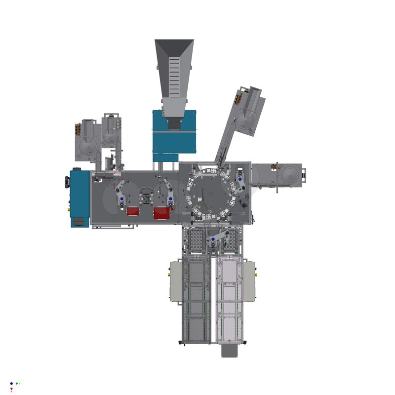
The assembly island realized by Hirata contains four SCARA robots and two palletizing systems from Hirata, a turning unit, a small and a larger freely programmable rotary indexing table as well as five spiral conveyors and some servo axes on an area of approx. 8 x 8 m. To ensure the flexibility of the system, all infeed, assembly and handling movements are freely programmable and the corresponding units are equipped with quick-change grippers. The entire system is controlled by a PLC, which is divided into two areas on the software side. One area is responsible for the pre-assembly of the strain relief, the other area processes the more complex control of the housing assembly for the normal connector and the low-cost variant. A Hirata-own controller is used as motion control for all four SCARA robots. Here all robot positions are stored, which are then approached by the commands of the PLC. The possibility to control up to four robot systems or up to 16 servo axes with one robot controller is not possible with many manufacturers, but provides a high cost saving potential. Also the pneumatics is divided. Each side of the plant has its own valve terminal so that the distances are short and fast switching cycles are possible. An employee can set up the system or call up data via a mobile operating panel and move relatively freely around the system. There are holders on the four sides of the unit in which the control panel can also be placed.
Clamping roller on the left, Connector housing on the right
For the normal plug version, the assembly starts simultaneously at two points of the system. On the left side, the strain relief (clamp roller with spring and clamp roller receiver) is mounted, on the right side the assembly of the plug housing with latch and grommet is started. In the middle of the system, these two pre-assembled units are brought together and mounted then. When mounting the low-cost variant, only the right-hand part of the assembly island works, because this plug is manufactured without strain relief and only two components (latching and grommet) have to be mounted in the plug housing.
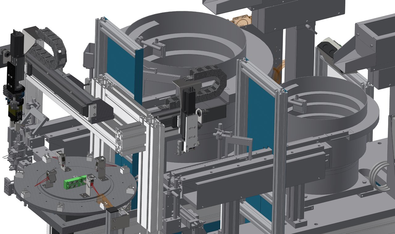

The assembly of the clamping roller starts at the small rotary indexing table in pos. 1 with the feeding of the clamping rollers via a spiral conveyor. A linear axis always removes a clamping roller and places it in a workpiece nest on the rotary indexing table. At pos. 2 the springs are also fed via a spiral conveyor, picked up with a mandrel, brought into position and pressed onto the clamping rollers. At pos. 3 the correct position of the springs will be checked by a vision sensor. At pos. 4, an AR-F 650 SCARA robot grips the components and brings them to a turning unit for mounting the clamp roller pick-up-unit. Here, the clamp roller pick-ups are fed by a spiral conveyor, removed by another SCARA robot (AR-F 500) and deposited in the assembly position. Now the rollers are pressed laterally into the pick-up-unit by two pneumatic cylinders. The the correct fit is checked by a vision sensor then. The SCARA robot AR-F 500 removes the parts thus joined and brings them to the large rotary indexing table (pos. 9) on the right side of the system.
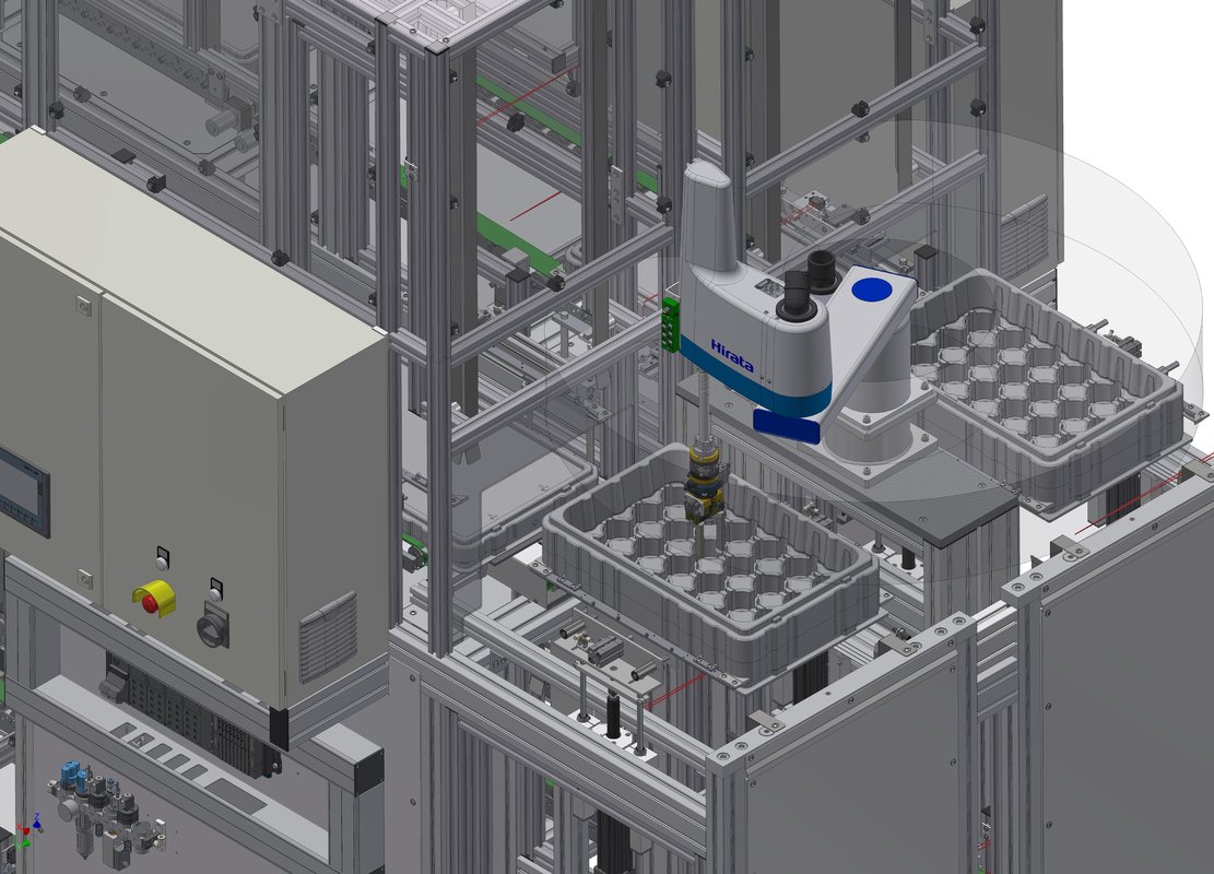
Connector housings will be added by the Palletizer
In the meantime, the connector housing was mounted on this large rotary indexing table. The assembly starts with the feeding of the injection-molded connector housings. The connector housings are provided in trays, which are stacked on a floor roller and pushed into a palletizer from behind. Here the trays are separated, a SCARA robot AR-F 650 removes the parts and transfers them to a vertically operating linear axis. This vertical linear axis is necessary to bridge the height difference of about 450 mm between the working level of the palletizer and the large rotary indexing table. The working height of the palletizer results from the sum of the height of the tray stack and the height of the bottom roller. The rotary indexing table is located at a height of approx. 1,000 mm, so that any necessary maintenance work can be carried out without any problems. The vertical linear axis also has a second task. It is equipped with a turning unit and rotates the plug housing by 180° so that the main assembly side of the component faces upwards. The linear axis places the component in pos. 1 of the rotary indexing table then. Pos. 2 is without function at the moment, another component may be mounted here later. At pos. 3 the latching is fed by a spiral conveyor and assembled by a second SCARA robot AR-F 500. For this purpose the robot is equipped with a special joining tool. Afterwards the correct fit of the latching mechanism is checked by a vision sensor (pos. 4). The grommet of the connector is mounted in the next position (pos. 5). A dual-axis system grips the grommet from the end position of the bowl feeder and places it on a servo cylinder, which now inserts the grommet onto the connector housing from below and snaps it into place. In the next step (item 6), this assembly is also checked again. Three tactile sensors move to the grommet from below and check whether it is straight. At the normal connector version, Items 7 and 8 on the rotary indexing table have no function.
Clamping roller receiver and housing are combined
In pos. 9 the pinch roller, which is pre-assembled on the left side of the system, will be inserted into the connector housing by the the SCARA-robot. By this way, the spring of the clamping roller is tensioned. This assembly step is immediately checked by a laser sensor. The last position of the large rotary indexing table (pos. 10) is the removal position. In this position there is also a vertical axis with a turning unit, which moves the now completely assembled component (OK-part) upwards, turns it and transfers it to the SCARA robot. The SCARA robot places the components back into trays, which are stacked again in a second palletizer, conveyed to the rear and moved out of the palletizer by a floor roller. NOK parts that have not passed at least one of the the test steps are sorted out at this removal position via a chute.
When the low-cost variant is installed, the left-hand area of the system is not in operation, because this variant does not require any additional strain relief. The assembly also starts at pos. 1 with the placement of the connector housing in the workpiece nest on the large rotary indexing table here. In pos. 3 the latching is mounted and tested (pos. 4) afterwards. In the next step, the low-cost grommet is fed in pos. 7 via a spiral conveyor. As with the normal connector variant, the grommet is joined from below via a two-axis system and a servo cylinder. A subsequent test is performed in pos. 8. Pos. 9 runs empty and in pos. 10 the finished low-cost plug is removed, turned and placed in the trays.
Low effort to changeover
The large rotary indexing table is equipped with three different workpiece nests for the three possible connector sizes at all positions. The nests are designed in such a way that even between type changes (normal plug to low-cost plug) no conversion is necessary. Together with the freely programmable infeed, the assembly- and handling movements, some still free assembly positions and the quick-change gripper systems used the entire assembly island is very flexible and can also be expanded for some subsequent assembly steps later on.